-
Technical Information (TI)
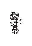
Proline Promag 10D Technical Information
|
English version - 02/2016 |
Electromagnetic flowmeter The highly cost-effective flowmeter, available as compact wafer.
| EN | |||
|
09/02/2016
|
|
|
|
|
15/07/2011
|
|
|
|
|
01/11/2009
|
|
|
|
|
31/03/2009
|
|
|
|
Language: |
English |
|
Version: |
09/02/2016 |
|
File size: |
612.2 KB |
|
File name: |
TI00081DEN_1416.pdf |