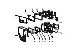
Specs at a glance
-
Input
1 x analogue 4...20 mA/HART®
-
Output
Not defined
-
Display
LCD 17 mm (0.67")
5-digit
7-segment bargraph
Plain text display for unit/TAG
Activatable backlight -
Power Supply
Loop powered
Field of application
The process indicator is available with 4 to 20 mA or with HART® protocol. In the HART® version up to 4 measured values of one sensor can be indicated in alternation. For this the indicator can be set as primary or secondary HART® master and actively inquire the values from the sensor. The small voltage drop of < 1V (< 1.9 V with HART®) is a huge advantage especially in Ex-applications, where in most cases only a reduced voltage is available.
Display of 4 to 20 mA measured values or HART® process variables in all industries
Panel-mount housing or field housing as local display
Scalable display value
With the "Level" or "Analysis" options, basic settings can be made on selected sensors and available measured values and units can be preset quickly and easily.
Benefits
Display of 4 to 20 mA measured values or optionally up to four of a sensor's HART® process variables in all industries; Use as primary or secondary HART® master
5-digit measured value display with 17 mm (0.67") character height with dimension and bargraph; backlight can be activated
Panel-mount housing (IP65) or field housing (IP66; Ex approval) as local display; Minimal installation depth
No external power supply required; Voltage drop ≤1 V (HART® ≤1.9 V)
Easy 3-key operation for configuring the device
International approvals; marine approval
SIL interference freeness acc. to EN 60508
Videos
Fundamental selection
-
Simple products
- Easy to select, install and operate
Technical excellence
Simplicity

-
Standard products
- Reliable, robust and low-maintenance
Technical excellence
Simplicity
-
Specialized products
- Designed for demanding applications
Technical excellence
Simplicity
Variable
| FLEX selections | Technical excellence | Simplicity |
|---|---|---|
Fundamental selection Meet your basic measurement needs |
Technical excellence
|
Simplicity
|
Lean selection Handle your core processes easily |
Technical excellence
|
Simplicity
|
Extended selection Optimize your processes with innovative technologies |
Technical excellence
|
Simplicity
|
Xpert selection Master your most challenging applications |
Technical excellence
|
Simplicity
Variable |
 Loading alternative products
Predecessor
-
-
Technical Information (TI)
TI RIA15
English version - 04/2023
Loop-powered 4 to 20 mA process indicator with optional HART® communication
EN 23/04/202319/07/201925/04/201810/06/201626/01/2015Language:
English
Version:
23/04/2023
File size:
1.3 MB
File name:
TI01043KEN_0823-00.pdf
-
-
-
Explosion Protection
Product family: Process displays
English version - 05/2022
Product root: RIA15- Region: Europe (ATEX) Approval agency: PTB Category: II 2 G Protection: Ex ib IIC T6 Gb
EN 10/05/2022Language:
English
Version:
10/05/2022
File size:
2.7 MB
File name:
PTB 12 ATEX 2017 X_Iss.1.pdf
-
-
-
Technical Information (TI)
TI RIA15
Loop-powered 4 to 20 mA process indicator with optional HART®
communicationEN 23/04/202319/07/201925/04/201810/06/201626/01/2015Language:
English
Version:
23/04/2023
File size:
1.3 MB
File name:
TI01043KEN_0823-00.pdf
-
-
-
Operating Instruction (BA)
BA RIA15
Loop-powered 4 to 20 mA process indicator
EN 23/04/202312/07/201901/05/201809/06/201621/01/2015Language:
English
Version:
23/04/2023
File size:
4.1 MB
File name:
BA01170KEN_0823-00.pdf
-
-
-
Operating Instruction (BA)
BA RIA15
Process indicator
EN 23/04/202308/06/201618/11/201426/07/201326/02/2013Language:
English
Version:
23/04/2023
File size:
1.9 MB
File name:
BA01073KEN_0723-00.pdf
-
-
-
Short Instruction (KA)
KA RIA15
Loop-powered 4 to 20 mA process indicator with optional HART®
communicationEN 23/04/202306/06/201626/08/201426/07/201326/02/2013Language:
English
Version:
23/04/2023
File size:
475.1 KB
File name:
KA01141KEN_0523-00.pdf
-
-
-
Ex Safety Instruction (XA)
RIA15, ORIA15
Ex ib IIC T6 Gb
EN 19/09/202230/07/2020Language:
English
Version:
19/09/2022
File size:
502.1 KB
File name:
XA02115KEN_0222-00.pdf
-
-
-
Ex Safety Instruction (XA)
RIA15 1Ex ib IIC T6 Gb X Safety Instructions
Safety instructions for electrical apparatus certified for use in
explosion-hazardous areas.EN 23/07/201812/09/2016Language:
English
Version:
23/07/2018
File size:
220.8 KB
File name:
XA01464KEN_0218.pdf
-
-
-
Ex Safety Instruction (XA)
Control drawing RIA15 cCSAus IS, NI
Control drawing RIA15 cCSAus IS, NI
EN 20/06/201715/04/2016Language:
English
Version:
20/06/2017
File size:
1.5 MB
File name:
XA01368KEN_0217.pdf
-
-
-
Ex Safety Instruction (XA)
RIA15 JPN: Ex ib IIC T6 Safety Instructions
Safety instructions for electrical apparatus certified for use in
explosion-hazardous areas.EN 28/02/2019Language:
English
Version:
28/02/2019
File size:
216.2 KB
File name:
XA01833KEN_0119.pdf
-
-
-
Ex Safety Instruction (XA)
Control drawing
Control drawing CSA IS, NI approval RIA15
EN 02/02/201509/10/2013Language:
English
Version:
02/02/2015
File size:
1.5 MB
File name:
XA01056KEN_0215.pdf
-
-
-
Ex Safety Instruction (XA)
FM Control drawing
Control drawing FM IS, NI approval RIA15
EN 20/06/201720/04/201509/10/2013Language:
English
Version:
20/06/2017
File size:
1.5 MB
File name:
XA01097KEN_0317.pdf
-


